
Table of Contents
Understanding the Basics: Flasher Relay Wiring Diagram
Understanding the Basics: Flasher Relay Wiring Diagram
Flasher relay wiring diagrams are essential for understanding the intricate electrical systems in vehicles, particularly in relation to Turn Signals and hazard lights. These diagrams provide a detailed blueprint of how the flasher relay interacts with other components, facilitating the smooth operation of these critical Safety features. Whether you’re a seasoned mechanic or a DIY enthusiast, grasping the fundamentals of flasher relay wiring is crucial for maintaining and troubleshooting automotive electrical systems.
| Nr. | Name |
| 9 | Auto Relay |
| Serial Number | Product |
| 4 | Auto Relays |
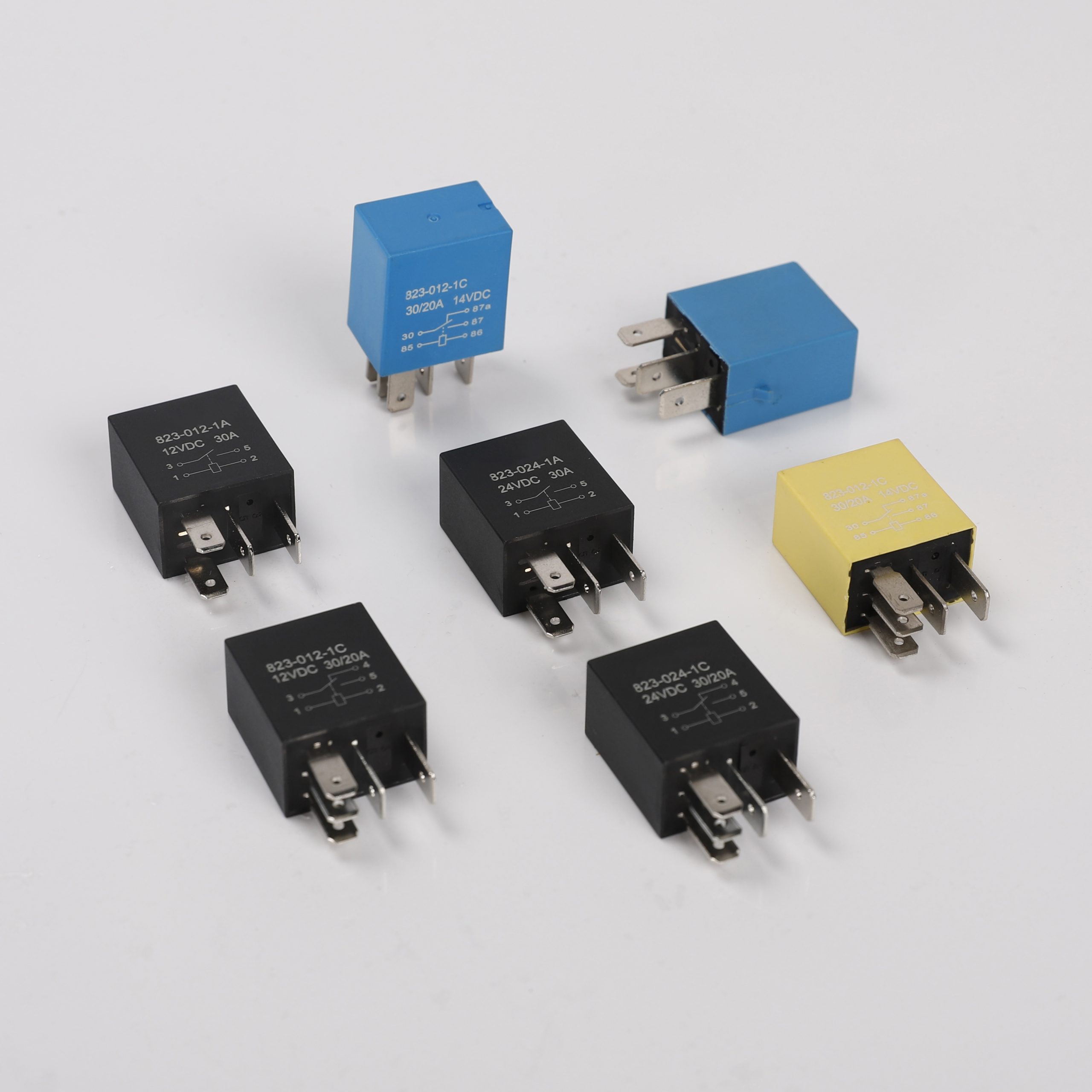
At the heart of the flasher relay wiring diagram is the flasher relay itself. This small but significant component is responsible for controlling the timing and sequencing of turn signals and hazard lights. By regulating the flow of electricity to the bulbs, the flasher relay ensures that these signals blink at the appropriate rate, alerting other motorists of your intentions on the road.
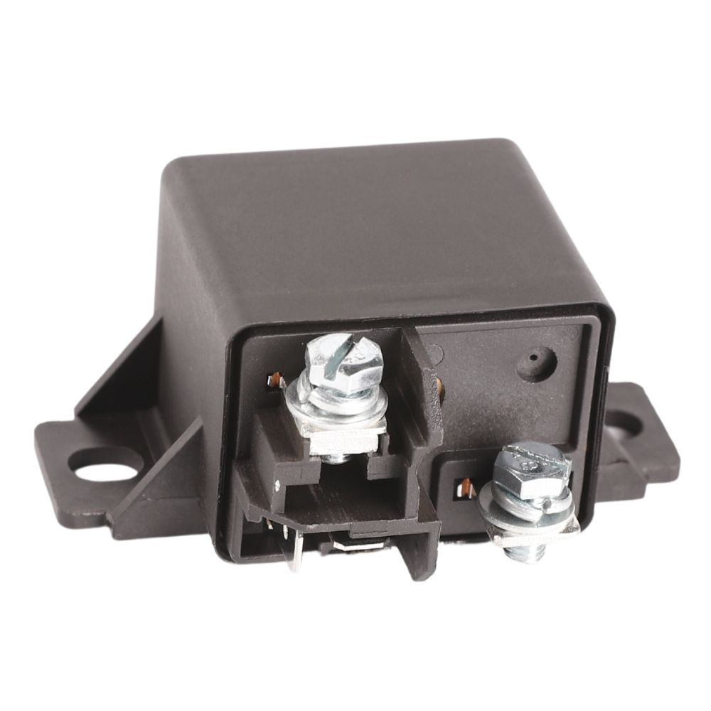
In a typical wiring diagram, the flasher relay is depicted as a rectangular or cylindrical unit with multiple Terminals. Each terminal serves a specific function, such as power input, signal output, and ground connection. Understanding the purpose of each terminal is key to deciphering the wiring diagram and troubleshooting any issues that may arise.
One of the most common configurations in flasher relay wiring diagrams is the use of electromechanical relays. These relays feature an electromagnet that activates a set of contacts when energized by an electrical signal. In the context of turn signals and hazard lights, the activation of these contacts results in the intermittent flashing of the bulbs, as dictated by the timing circuitry within the relay.
| No. | Name |
| 3 | Auto Relays |
Translating the abstract symbols and lines of a wiring diagram into a physical understanding of the vehicle’s electrical system requires a keen eye for detail and a solid grasp of electrical principles. Each wire, connector, and component depicted in the diagram plays a specific role in the overall functionality of the system. By following the pathways outlined in the diagram, technicians can trace faults and perform repairs with precision and efficiency.
In addition to understanding the internal workings of the flasher relay, it’s also crucial to grasp its interaction with other components within the vehicle’s electrical system. For instance, the relay may receive input signals from the vehicle’s turn signal switch or hazard light switch, triggering the appropriate flashing sequence. Likewise, the relay may interface with fuse boxes, power distribution modules, and other control units to ensure proper operation under varying conditions.
Amazon relay box Truck requirements further underscore the importance of comprehending flasher relay wiring diagrams. These requirements dictate the standards and specifications that must be met by commercial vehicles operating under the Amazon Prime delivery network. While the specifics may vary depending on the region and type of vehicle, adherence to these requirements is essential for ensuring the safety and reliability of delivery operations.
In conclusion, flasher relay wiring diagrams are invaluable resources for understanding the intricate electrical systems found in vehicles. By deciphering these diagrams and grasping the fundamentals of flasher relay operation, technicians can diagnose and repair electrical faults with confidence and precision. Whether you’re a professional mechanic or a DIY enthusiast, mastering the basics of flasher relay wiring is a critical step towards maintaining and troubleshooting automotive electrical systems.